The first step
Those who love electronics
Oscilloscope is very useful to them
Today I will tell you how to make Oscilloscope.
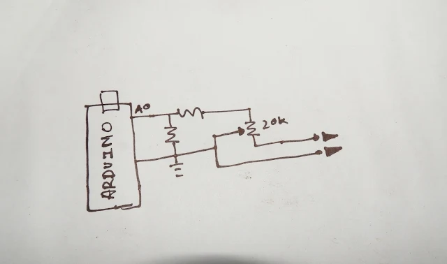
therefore i had made a circuit out of arduino board,
i connect two alligator clip with the arduino board,
i use the because for making my work easy to measure any wave frequency .
So i connect my USB cable with my laptop
and the other end to the ardino.
so you can see the circuit is running.
now i open the PC Scope software in my laptop.
for now it looks like this.
second step
Arduino code
const int analogInPin1 = A0; // Analog input pin that the potentiometer is attached to
static int ctr,flag_tog;
static unsigned char adcval;
void setup()
{
Serial.begin(115200);
pinMode(13, OUTPUT);
ADCSRA = 0; // clear ADCSRA register
ADCSRB = 0; // clear ADCSRB register
ADMUX |= (0 & 0x07); // set A0 analog input pin
ADMUX |= (1 << REFS0); // set reference voltage
ADMUX |= (1 << ADLAR); // left align ADC value to 8 bits from ADCH register
// sampling rate is [ADC clock] / [prescaler] / [conversion clock cycles]
// for Arduino Uno ADC clock is 16 MHz and a conversion takes 13 clock cycles
//ADCSRA |= (1 << ADPS2) | (1 << ADPS0); // 32 prescaler for 38.5 KHz
ADCSRA |= (1 << ADPS2); // 16 prescaler for 76.9 KHz
//ADCSRA |= (1 << ADPS1) | (1 << ADPS0); // 8 prescaler for 153.8 KHz
ADCSRA |= (1 << ADATE); // enable auto trigger
ADCSRA |= (1 << ADIE); // enable interrupts when measurement complete
ADCSRA |= (1 << ADEN); // enable ADC
ADCSRA |= (1 << ADSC); // start ADC measurements
}
ISR(ADC_vect)
{
adcval = ADCH; // read 8 bit value from ADC
}
void loop()
{
Serial.write(adcval);
ctr=0;
flag_tog = !flag_tog;
digitalWrite(13, flag_tog);
}
}
Third Step
I had put the coding in the arduino,
so now we just need to connect the aurdino to the software.
now i click on the connect button, it will take a while and now you can see the wave line.
now i will check the 555ic's PWM frequency, it should be in between 50 to 60 hertz
I connect the ground alligator clip to the ground pin, and frequency alligator clip to the IC’s 3rd pin which is IC’s output pin.
So now You Can See The Square Wev line.
and also the frequency, between 50 to 60 hertz which i told you before.
you can also change the scale by clicking on the nobs .
okh and now i want to check the alternative current,
now I take a 6.0.6 transformer
and now i will check the voltage
so you can see here is 6 volts showing on one side, and together 12 volts.
and i connect the Arduino Oscilloscope clip on one side of the transformer.
you can see the wave and also the volt.
it is showing 6 volts as on the meter .
and frequency under 50 hertz
and i connect clip on both on the sides of the transformer and it is showing 12 volts and same hertz.
it is really very simple to make the aurdino Oscilloscope .
you can see this diagram i made the circuit same as this diagram.
you have to follow that from 0 analog pin of aurdino .
you have connect 570 resistor for the safety of the aurdino.
and another 10k resistor to ground to analog zero for noise clearation.
i connect a pre set on the other side of the 570k resistor to adjust the frequency as i want.
so now i open the software and put the code,
it is not as perfect as the Oscilloscope , which you can get in the stores.
you can use it as a basic Oscilloscope which is made by yourself.


hi great job
ReplyDeletecan u share the software plz
Do you write the arduino code? Or have found it over internet???
ReplyDelete