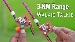
I have done many calculations, the correct inductor is 22 microhenry but I don't have it,
Are you afraid to make coils?
Trust me there's nothing to fear from the coil, it's so simple, you just wind it in any way, It will work properly, no problem.
That's why I'm using a Straw here,
Its diameter is 5mm. 6mm or 7mm no problem.
I am using 0.30mm copper wire here.
You only need to twist 8 times, and the centre tap will be right in the middle
I forgot to mention, I used 0.33 copper wire to do this.
Anyway, let's try to make a transmitter.
This type of schematic is not very difficult.
Since I want a bit more range, so I have to do something different in that case
This kind of schematic looks very simple but actually, they are not simple,
Note that, many complex formulas work in this type of circuit.
For example, here LC system, input-output section, regenerator register, and current limiting register.
Here I used the BD139 transistor. It is powerful enough for my task as I am going to use high voltage here.
I believe everything will work out properly.
But in your case, it will also work properly because I have carefully placed each part here.
Now I want to make a circuit that works perfectly.
here is the coil that I made. this is my capacitor, whose value is 1PF to 40PF.
Since this is a single-stage transmitter, proper selection of transistors is very important.
I am going to use the BD139 transistor here.
It can handle more current, meaning it will transmit over longer distances.
after connecting the 3.7-volt battery
I hooked up my oscilloscope with this circuit
and you can see the frequency is now approx 17 Mhz
if I tune this variable capacitor slowly then you can see the frequency is slowly increasing, which means I can tune my desired frequency yes you can see I can set my desired 27Mz frequency,
on the other hand, you might ask why I don't use 27Mhz crystal.
it will be easier to choose the desired frequency.
no problem you will get your answer later.
if you look closely then you can see my wave is not accurate sign wave
because I need to make an LC filter to create a proper sine wave
now, if I touch this RF Probe with this circuit then you can see my LED light is glowing very well,
which means 27Mhz frequency is resonant
Step Two = How to work a Receiver?😎
okay, our transmitter section is ready, but what about the receiver?
The receiver section and transmitter section are pretty much similar.
just you have to make a voltage divider to get listenable audio.
this is not a proper way to build a receiver but in this way, you can still make a receiver
The advantage of this way is that you don't have to use your brain and your money too much.
so for this why I am not using this LM386 audio amplifier IC? This IC is very good for this kind of Radio application
for testing purposes, I am going to use these Telescopic Antennas,
These antennas are not suitable for 27 MHz. but for now, I will use it
and this is very important, use a 47 PF capacitor for this transmitter antenna, because this PF can block DC volts.
so now I will connect both antennas with this transmitter and receiver after I place these Antennas like this
for transmitting signal I am going to use my function generator.
Now I set my function generator on 1khz.
then connect the 1khz signal with this transmitter.
okay, finally, my transmitter and receiver set-up is ready.
Step Three = Check Receiver transmitter?😎
so let's check this out can my receiver receive the signal from the transmitter?
here you can see when I tune this variable capacitor my receiver received the correct frequency here I tune this transmitter.
but just checking the purpose I doing it.
but in your case, you will fix this transmitter frequency to 27 MHz and tune your receiver frequency to receive data.
If you move this receiver antenna, you may have problems but that doesn't mean it won't work from a distance.
the funny thing is when I connect this RF Prope to this transmitter's antenna.
then the RF probe LED is glowing when the frequency is fully resonant otherwise not
anyway, everything is working pretty well, but this is not for a practical circuit.
because everything is not decorated so I will make it in a great way
Step Four = Final Receiver and transmitter?😍
I gathered all the necessary components that I required.
even modified the coils because I needed more range,
Transmitter Update Schematic Download
here you can see I added an extra stage for the antenna this is what covers a wide range.
I used 3d 3D-printed shell for this coil and even applied glue for more secure

As a result of all the experiments I have done so far, I will mount everything on this copper dot board,
Maybe you are wondering why this 27Mhz crystal?
Think the experiment is still going on.😁
Let's see how the crystal works? It is a 27 MHz crystal and after installing it if I tune my frequency I hope there is no significant difference.
But by modifying this circuit it is possible to make 27 Mhz frequency with crystal.
Anyway, I don't need the crystal anymore.
still, I can do my desired 27 Mhz frequency which is a lot more stable.
as well as I will make another stage for a microphone to transmit my voice.
Step Five = How to make An 27Mhz Antenna?😍
for 11 Meter wavelength I have to make an 18.4 feet-long antenna for better communication.
this is just Madness from making an 18-foot-long antenna,😛
but this is also important.
that is the reason I take 18 feet-long 0.3 mm copper wire for making a spiral Antenna
I need 7 mm thickness pipe so that is why I choose straw,
To make it 2 feet long this straw I used a 3D printed splitter
However, this time the 18 meters of copper wire should be twisted between these two feet of pipe.
You need to leave a 6-inch gap at the end of the pipe to allow proper magnetic wave propagation.
this is the NRF24L01 transceiver module. this model produces 2.4Gh
I needed just this antenna from this model.
this is not useable at least for me because I am working now at 27 Mhz frequency,
I needed just this 50 ohms PLL connector
Now the question is. Is it profitable to make?
Yes, it must be correct to make it I limit it to only 2watt of power,
As a result, you can communicate it at least a 3 km range if your antenna is correct.
with that, this system also has a few problems.
because my radio receiver is not too much perfect.
when I close the transmitter that receiver produces a lot more noise for too much gain.
and if I am far from the transmitter then the sound quality fades,
this is the main problem because my receiver was not made in the Superheterodyne process, this tactic is the revolution of the radio technique.
That was my mistake................
Update Receiver Schematic Download


please do not enter any spam link in comment box