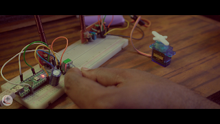
In my previous video, I mentioned how to calculate an LC circuit and make a proper coil, how to tune the correct frequency, how to make a perfect antenna, and even how to communicate with each other. but that was only Radio Communication.
Data means the PWM signal and even its duty cycle control. that means how to connect a radio with Arduino
if you want to know how to work the transmitter and receiver then obviously you have to read this article ( 27 Mhz RF transmitter and receiver) then you will understand it better.
How to transmit and receive digital data via radio?
this is my Rx and TX schematic to transfer data.
Here this transistor is working as an on-off switch of the transmitter.
When switching on the transmitter generates 27Mhz EMF.
When off then there is no EMF.
Similarly, when the transistor is switched on again the EMF will be generated.
Just like that.
This is what the receiver is decoding as data, as 0 and 1.
Let's try to understand the receiver section.
We get a feeble signal from the receiver section
For that reason, I used the LM358 Op-amp to amplify the signal.
I have used 1 site of op-amp to amplify the weak signal of the receiver,
the other site works as a voltage compeer, to get the correct data output.
How to make a 27-Mhz coil?
First of all, I have Removed the variable capacitor from my circuit because it is not easily available.
Instead, I'll use variable inductors here.
This is what you can take out of the children's toy car.
To make this inductor you need to wind eight times with 0.15 mm wire,
and your coil is ready.
How to make RX & TX?
The previous video circuit and this video circuit are similar with only a few changes
Again, if you haven't read the previous (Article), read it now, otherwise, you won't understand anything, even might have trouble making it.
component purchase link 1= Aduino Nano 2= Servo Motor 3= Rotary pot 4= 3.7 V Lithium-ion Battery 5= Resistors 6= capacitors
after all calculations, I make a rough transmitter
run it the first time I am going to use 3.7 volt Lithium battery
next, i Connect the oscilloscope to see the frequency
Since I need 27-Mhz I will tune to 27-Mhz.
Because it is the only public free frequency in India.
Now I understand that my transmitter is working properly.
So now I will mount the ON OFF transistor which is for the data signal.
And this is my final transmitter and receiver.
let's check this out
433 MHz Module vs My 27Mhz Module
It is a 433 MHz module.
This is a 27 Mhz module made by me,
So let's check which module is better.
433 MHz module can transmit digital data up to 5 kHz.
and this module can transfer data of more than 8 kHz maximum.
it is also usable for up to five kHz.
but for audio transmission this 8 Khz frequency is usable
Even with Arduino, you can communicate very easily with my transmitter and receiver.
Also if you think you want to receive without Arduino in the receiver section you can do that too.
On the other hand, you cannot receive digital data in this way in a 433 MHz module
Because its output signal does not very high amplitude.
Even my 27 Mhz module can transmit and receive voice very well.
However, the 433 Mhz module cannot transmit or receive voice very well. because the limitation of data transfer
This 433 Mhz module can only transmit and receive up to a few meters but my 27Mhz module can cover a distance of at least a kilometer.
which I discussed well in my previous article
I want to do some more experiments and if everything works properly, maybe you can buy it from me.
why do my transmitter and receiver work great?
Lambda is your answer This is the main reason my transmitter works great
By lambda, we can measure the web length
of this 27 Mhz tx oxalate in this way.
even these 433 megahertz transmitters oscillate similarly.
but the major difference is that 433 TX can oxalate 433 million times per second.
on the other hand, my one oxalates 27 million times per second.
The distance between two webs is called wavelength.
How large this wavelength is depends on the frequency of the transmitter
Here, my transmitter web length is 11.1 meters but on the other hand, 433 mhz transmitter wavelength is only 1.4 meters.
This is why my transmitter is winning
the disadvantage of my transmitter?
my transmitter produces very big waves so that is why my web easily can pass through trees and buildings, As a result, we can communicate over great distances.
other hand, a 433Mhz transmitter produces just only 1.4m wave,
which means this is very small As a result the signal will fade after traveling some distance
It is true, the distance is covered more but it also has its disadvantages.
If your frequency is low then the size of your antenna must be increased.
that is why In my previous video, I used about 18 feet of copper wire for the antenna.
But on the other hand for 433MHZ only 10-inch copper wire is enough.


please do not enter any spam link in comment box